
Introduction
The MAX2871 WIFI board allows the user to test and evaluate the performance of the MAX2871
frequency synthesizer chip. This is done wireless via a WIFI or hotspot connection.
The heart of the MAX2871 board is the MAX2871 frequency synthesizer chip that is capable of synthesizing frequencies from
22 MHz to 6.3 GHz while maintaining superior phase noise and spurious performance.
An ESP32 controls the MAX2871 and has a built in web server that allows the user to communicate using a WIFI connection.
The ESP32 also contains the test software. Using an internet browser the user can access the test software page from any smart device or PC.
Most of the parameters of the MAX2871 can be controlled and performance can be verified in real time.
Additionally all register values are being displayed.
This will assist the user in correctly programming the MAX2871 in their own applications.
A si5351a clock generator is connected to the reference input (REF IN) of the MAX2871.
The si5351a is controlled by the ESP32 and can generate frequencies between 10 MHz and 80 MHz.
The board has a micro USB power supply connector and a LiPo battery connector for easy power supply options.
Included on the board is a LiPo battery charger, a supply voltage and current monitor.
Quick start up guide MAX2871 WIFI board
WHAT YOU WILL NEED
| 1 | MAX2871 WIFI board |
| 2 | smart device (smartphone, tablet, etc..) or PC with internet browser |
| 3 | micro USB cable with charger or LiPo battery with JST-PH connector |
SETUP COMMUNICATION BETWEEN YOUR BOARD AND YOUR SMART DEVICE OR PC FOR THE FIRST TIME
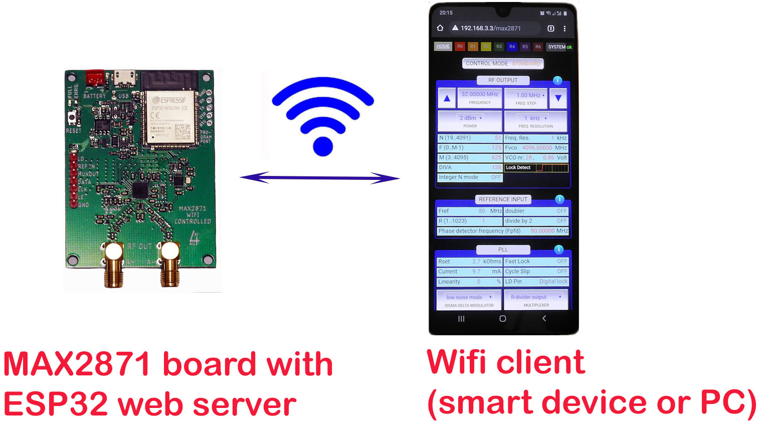
Figure 1. Hotspot connection between MAX2871 board and smart device
Take the following 3 steps:
| 1 | Plug the USB or battery cable into the MAX2871 board. Within a few seconds the 'power on' LED (blue) and one or 2 green LED's will light up. |
| 2 |
On your smart device or PC, go to the wireless & network settings. Select the 'max2871_101' network.
Type in the password: 123456789 It may take a while before the MAX2871 board is detected. In that case please refresh or re-open the network selection page. You will now be connected to the MAX2871 board in hotspot mode. This means that you have a private connection. You are not connected to the internet. Please note that your smart device or PC might ask you if you want to stay connected without internet. In that case answer YES. |
| 3 |
Open your internet browser and open the following page: 192.168.3.3/max2871 The MAX2871 application will show up. You can use the mouse or touch for navigation and control. |
GOOD TO KNOW
| • | Check the system page for the status of the WIFI / hotspot connection and the MAX2871 board. On board Voltage, Current and Connection should all be ticked (✔). If there is no connection the system status will change into a red X. |
| • | There are 3 control modes: 'standard', 'advanced' and 'sweep'. Press the 'control mode' button to toggle between them. |
| • | Press the blue round info buttons for more information about the buttons and fields within a section. Press again to close the help text. |
| • | All parameter settings will be stored in the cache of your browser. If you close and re-open the web page, settings from your previous session will be restored. |
| • | If you connect another smart device or PC to the board, the old connection will be closed. |
| • |
In case that your smart device or PC disconnects from the board please do the following to re-connect: Check that the MAX2871 board is powered on. Check that your smart device or PC is connected to the max2871_101 network and you have the web page 192.168.3.3/max2871 open in your browser. Go to the 'SYSTEM' page and press the 'CONNECT' button in the 'connect to hotspot' section. If that still doesn't work reset the MAX2871 board and refresh the browser. Then repeat the steps above. |
| • | For more info about how to use the software, the hardware and how to connect to WIFI please consult the following chapters. |
MAX2871 board hardware
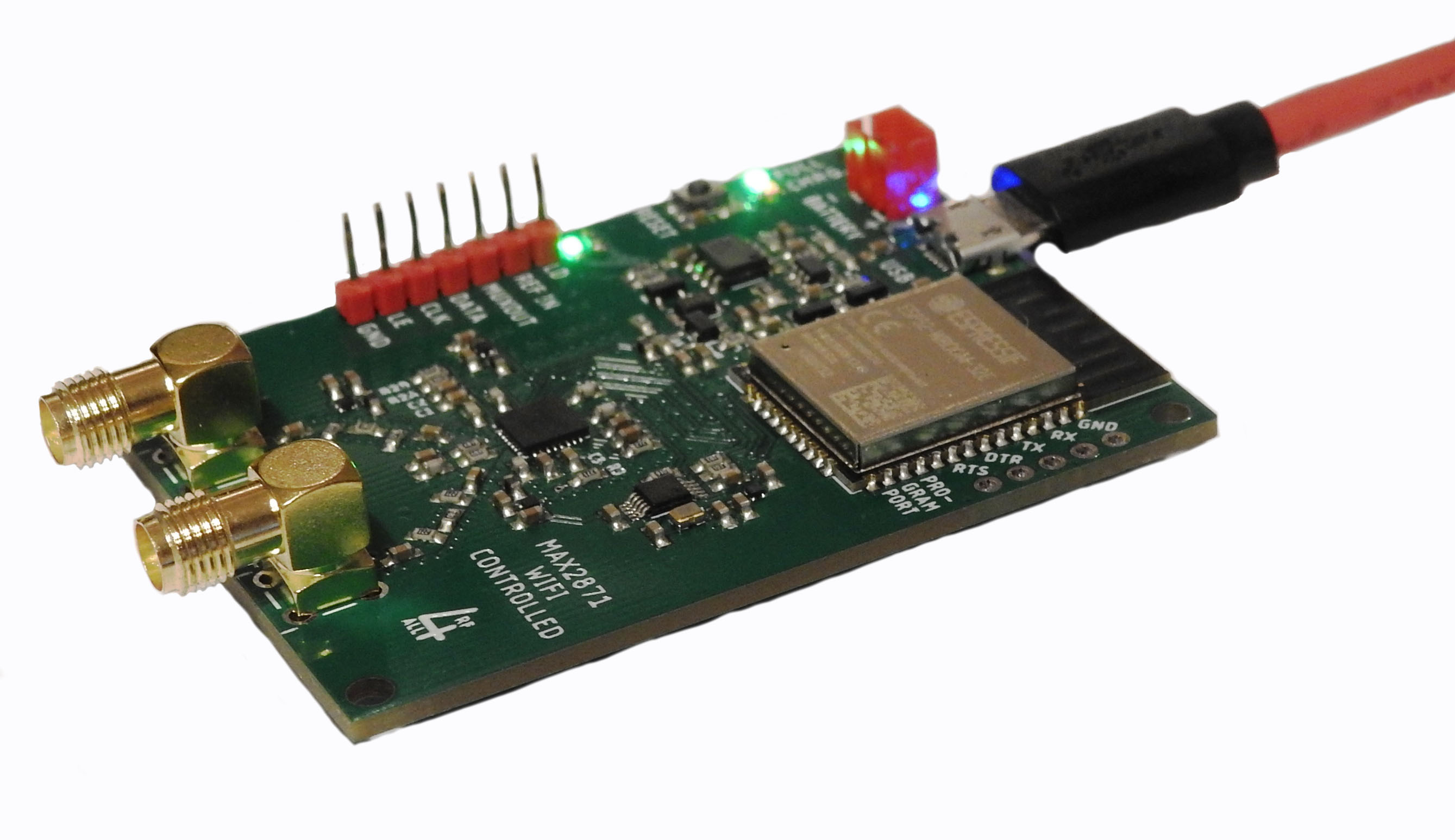
Figure 2 shows the main components, inputs and outputs of the MAX2871.
Care has been taken in designing the board so that the full potential of the MAX2871 can be explored in the frequency range from 22 MHz till 6300 MHz.
For highest frequency stability a stable and low drift TCXO clock is used as reference input for the MAX2871.
Ultra low noise and separate power supplies are used for the PLL, RF, charge pump and TCXO.
This results in low phase noise. And 3 dB attenuators have been added to improve output impedance matching over the entire frequency range.
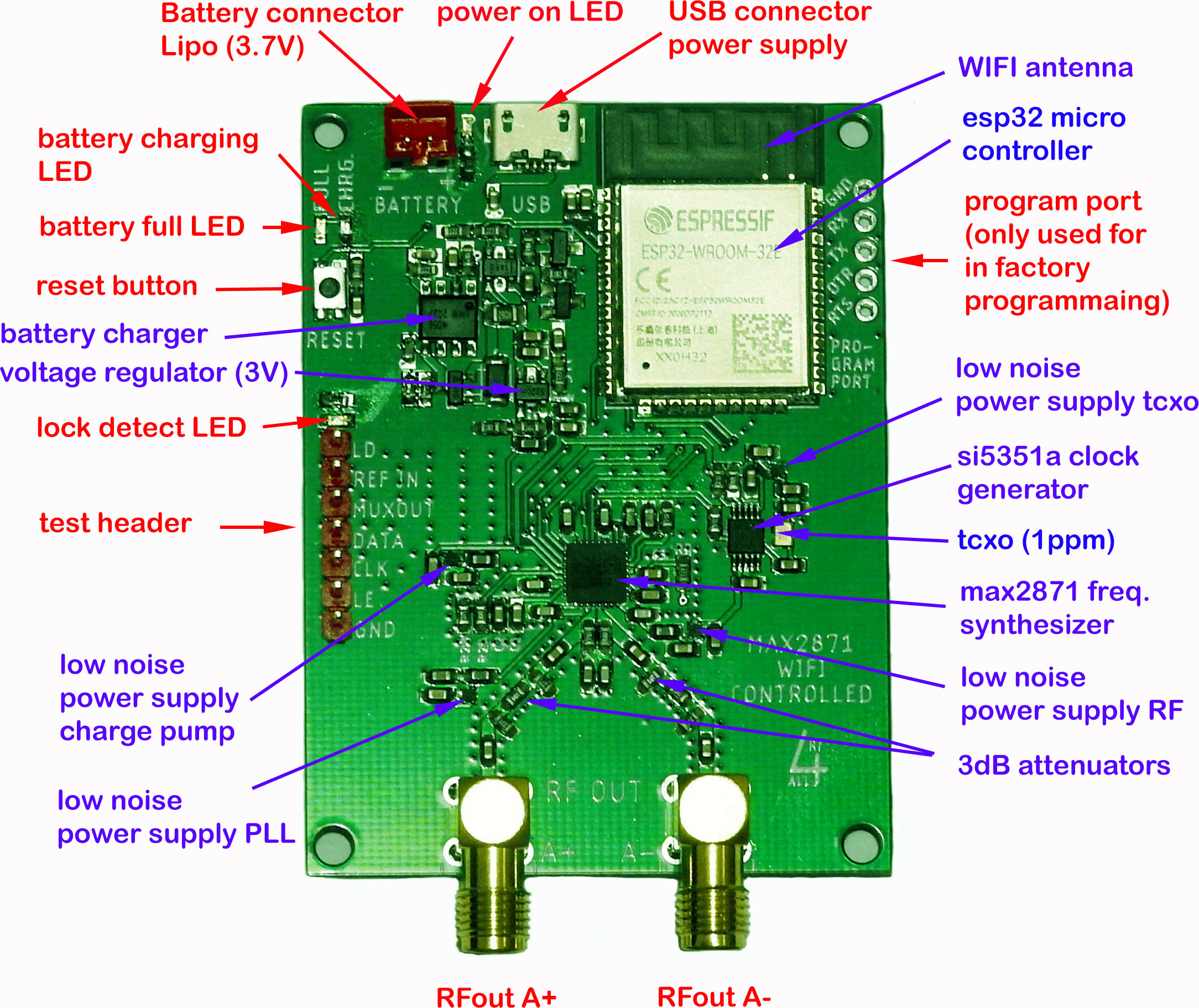
Figure 2. the MAX2871 WIFI board. in red: inputs/outputs, in blue: the main on-board components
The ESP32 microcontroller is pre programmed. It contains the firmware that reads and writes the MAX2871 registers.
It contains the server software that enables WIFI communication and allows the user to communicate via a internet browser.
It also measures the board's supply voltage and current consumption. This can be monitored with the test software.
The test pin header, see table 1, allows access to the MAX2871 board signals.
| TABLE 1. TEST HEADER PINS.
these are outputs and for measurements only! |
|
| LD (lock detect) | This pin is connected to the MAX2871 lock detect pin. It is logic-high when the PLL is locked, and logic-low when unlocked. |
| REF IN | This pin is connected to the MAX2871 Reference Frequency Input pin. |
| MUXOUT | This pin is connected to the MUX pin of the MAX2871. The function of this pin can be set with the test software. |
| DATA | This pin is connected to the DATA pin of the MAX2871. The Serial Data Input can be monitored. |
| CLK | This pin is connected to the CLK pin of the MAX2871. The Serial Clock Input can be monitored. |
| LE | This pin is connected to the LE pin of the MAX2871. The Latch Enable Input can be monitored. |
| GND | Digital ground connection. |
The MAX2871 has dual differential open-collector RF outputs.
On the MAX2871 board one pair is enabled and connected to the RFoutA+ and RFoutA- SMA connector outputs.
The phase difference between both outputs is 180 degrees.
Specifications can be found in table 2.
| TABLE 2. MAX2871 BOARD SPECIFICATIONS | |
| RFout frequency range | 22 MHz till 6300 MHz |
| RFout frequency resolution | 10 Hz (22-46.875 MHz), 20 Hz (46.875-93.75 MHz), 50 Hz (93.75-187.5 MHz), 100 Hz (187.5-375 MHz), 200 Hz (375-750 MHz), 250 Hz (750-1500 MHz), 500 Hz (1500-3000 MHz), 1 kHz (3000-6300 MHz) |
| RFout power | -7dBm, -4dBm, -1dBm, 2dBm |
| RFoutput impedance | 50 ohms for each output port |
| PLL divider mode | integer-N mode, fractional-N mode |
| REF IN frequency (clock) | 10 MHz till 80 MHz, 1kHz resolution |
| Frequency stability | 1 ppm, based on temperature controlled clock oscillator (TCXO). |
| PLL filter bandwidth | 40 kHz |
| Lock time | 350 µs (phase detector frequency = 4 MHz), 100 µs (phase detector frequency = 140 MHz) |
| Power supply |
Supply voltage: 3.3 till 5.5 Volt Current consumption: 200 mA (output power off), 270 mA (output power on) Connector type: micro USB, LiPo JST-PH |
| Voltage and current monitor |
power supply voltage: 3 till 5.5 Volt, 10 mV resolution supply current into 3 Volt regulator: 0 till 800 mA, 1 mA resolution |
| Communication | WIFI mode (STA) 2.4 GHz, Hotspot mode (AP) 2.4 GHz |
| Battery charger | Maximum battery charge current: 800 mA. Maximum LiPo battery capacity: 3600 mAh. |
| Operating temperature | -25° ... 80° Celcius |
| Dimensions | Dimensions: 49 mm x 66 mm x 13 mm |
| Weight | 20 grams |
MAX2871 software and Graphical User Interface
The test software allows the user to control most of the MAX2871 parameters and read or write the registers, see table 3a and 3b for the full list.
The user interface setup is shown in figure 3.Both mouse and touch control is enabled.
There are 3 control modes: 'standard' for semi automatic parameter control, 'advanced' for full parameter control and
'Sweep' for frequency sweeping applications. Toggle the button to change modes.
For each section help text is available by pressing the info button. For additional information about the MAX2871 parameters please
consult the MAX2871 datasheet.
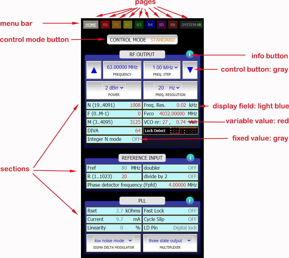
Figure 3. Graphical User Interface naming conventions
| TABLE 3a. TEST SOFTWARE - CONTROL PARAMETERS (please check the MAX2871 datasheet for more info.) |
|
| RF OUTPUT | Frequency, Resolution, Power, N+F/M divider, Diva, VCO frequency |
| REFERENCE INPUT | Ref_in frequency, R divider, Doubler, Divide by 2, Phase detector frequency |
| PLL | Charge pump current, Linearity, Cycle slip, Fast lock, Fast lock timeout, Lock detect pin, Sigma delta modulator noise mode, Multiplexer |
| SWEEP FUNCTION | Sweep time, sweep number of samples, Continuous mode, One shot mode |
| TABLE 3b. TEST SOFTWARE - DISPLAY FIELDS | |
| MAX2871 BOARD | Power supply voltage, Current, Status WIFI connection |
| MAX2871 CHIP | Lock time, Die Identification, Die temperature, VCO number, VCO voltage |
| MAX2871 REGISTERS | Registers 0...6 |
The values of the registers can be found at the pages R0...R6.
The user can change certain parameters and check the corresponding change in register values
in real time. In figure 4 register R5 is shown.
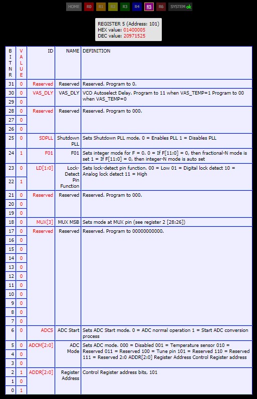
Figure 4. R5 register page
The system page, see figure 5, displays the MAX2871 board status, table of register values, the WIFI setup box and the Hotspot connect box.
If WIFI or Hotspot connection is lost the user can reconnect with the connect buttons.
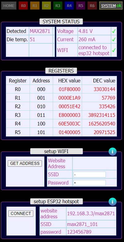
Figure 5. System page
All parameter settings will be stored in the cache of your browser. If you close and re-open the web page, all settings
from your previous session will be restored.
Connecting to the MAX2871 board in hotspot mode
Figure 6. Hotspot connection
The MAX2871 board has an active built-in hotspot. A hotspot connections allows you to communicate with the board privately and without the need for a WIFI network (see figure 6).
To connect your smart device or PC to the hotspot take the following steps:
| 1 | Power on the board. |
| 2 | On your smart device or PC select the hotspot network of your board: 'max2871_101'. In some cases it might take a while before the board is detected. In that case please re-open or refresh the network selection page. |
| 3 | Enter the network security key / password: 123456789 |
| 4 | After a few seconds you should be connected to your board. Please note that your smart device or PC might ask you if you want to stay connected without internet. In that case answer YES. |
| 5 | Open your preferred web browser and visit the following page: 192.168.3.3/max2871 |
| 6 | The MAX2871 web page will show up. In the menu bar the system status icon will show a green 'OK' |
Connecting to the MAX2871 board through WIFI
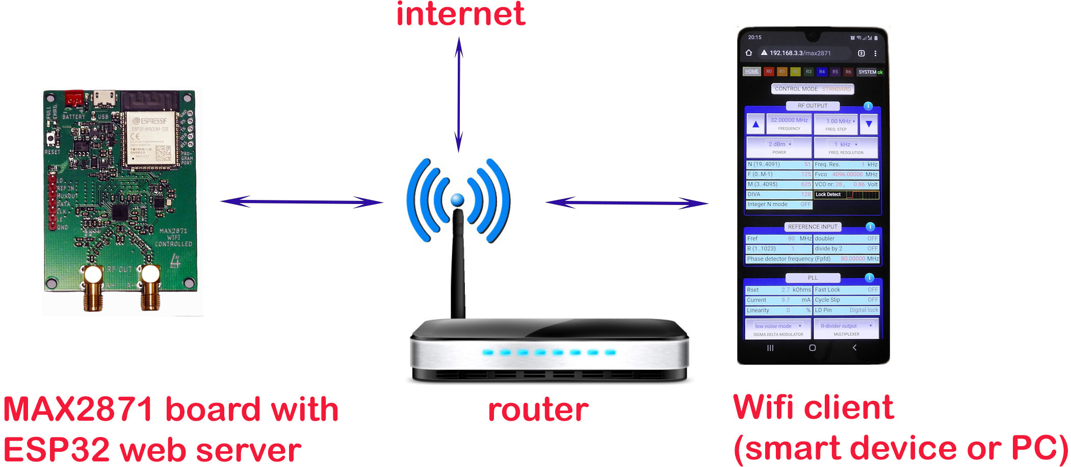
Figure 7. WIFI connection
The board can be connected to your local WIFI network, see figure 7. The advantage of connecting to WIFI, compared to the hotspot mode, is that you have access to internet.
If you have previously setup a WIFI connection and like to re-connect simply open the board's web page. Connection should be made automatically.
It you like to connect your smart device or PC to the board through a WIFI network for the first time, or to a new WIFI network follow the steps 1..6 below:
| 1. | Power on the MAX2871 board. |
| 2. | First connect to the hotspot, following the steps in the 'Connect to hotspot' section above. |
| 3. | Once connected to the hotspot select the 'system' page. Within the 'system' go to the 'setup WIFI' section. Type in the SSID and password/network key of your WIFI network. Then press 'GET ADDRESS'. |
| 4. | After a few seconds the WIFI website address will be shown. Make a note of it. |
| 5. | Now go the wireless/network settings page and connect to your WIFI network. Then, in your internet browser, open the WIFI website address from step 4. |
| 6. | After a few seconds you should be connected to your board and the web page opens. In the menu bar the system status icon will show a green 'OK'. |
The board will store your WIFI details. When you start a new session the board will automatically try to re-connect to your WIFI network.